Suspended Ceiling T Grid Manufacturer From China

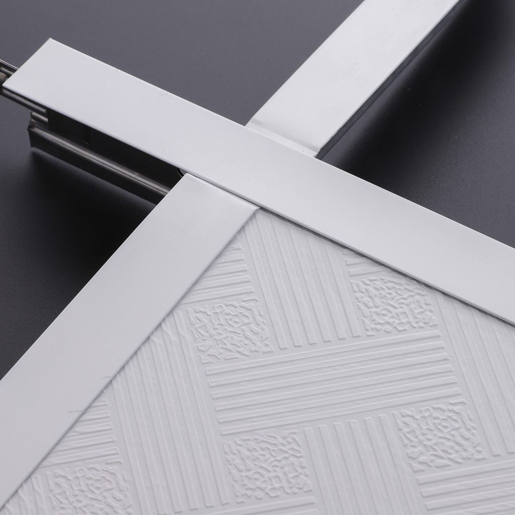
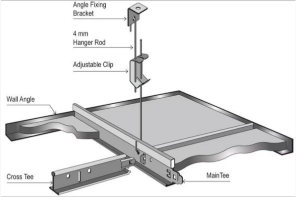
T GRID Ceiling Profiles is made from hot dipped galvanized steel, pressed to T shape after cooling, baked paint on surface finish, it is suspension false ceiling consisting of the main tee, cross tee, and wall angle to make the grid system to support the lay-in ceiling tiles. Mostly applied in the public buildings such as office, hospital, classroom, airport and so on.

FEATURES OF SUSPENDED CEILING T GRID

∗ High grade galvanized steel as main material, non-deforming, fadeless, moisture proof and anti-corrosive.

∗ Strong close fitting, high symmetry

∗ High load capacity

∗ Easy and fast installation, save installing time and labor cost

∗ Large production line and strict product inspection, larger quantity and better quality are available

SPECIFICATION AND TECHNICAL DATA

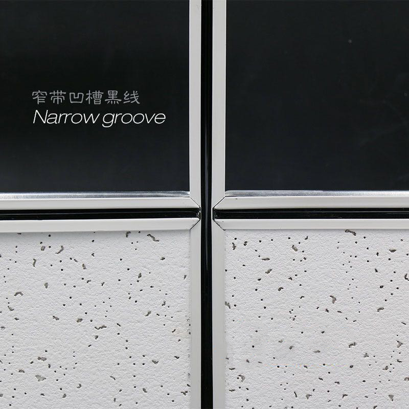
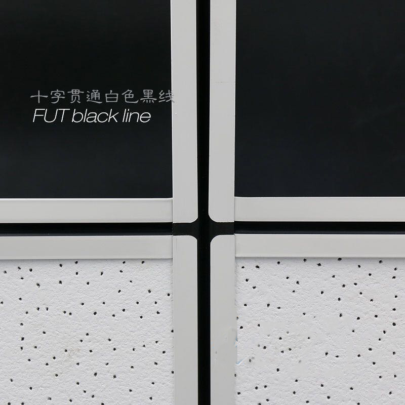
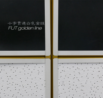
Narrow Plane 32 Specification Narrow Notch 32 (White/Black) Specification Solid Notch 32 Specification
Main Tee 32*14*3600 Main Tee 32*14*3600 Main Tee 32*14*3600
Cross Tee 32*14*600 Cross Tee 32*14*600 Cross Tee 32*16*600
Cross Tee 32*14*1200 Cross Tee 32*14*1200 Cross Tee 32*16*1200
Wall Angle 20*15*3000 Wall Angle 20*15*3000 Wall Angle 20*15*3000
Narrow Plane 38 Specification Narrow Notch 38 (White/Black) Specification Solid Notch 38 Specification
Main Tee 38*14*3600 Main Tee 38*14*3600 Main Tee 38*16*3600
Cross Tee 38*14*600 Cross Tee 38*14*600 Cross Tee 38*16*600
Cross Tee 38*14*1200 Cross Tee 38*14*1200 Cross Tee 38*16*1200
Wall Angle 20*15*3000 Wall Angle 20*15*3000 Wall Angle 20*15*3000
Wide Plane 32 Specification Wide Notch 32 (White/Black) Specification Solid Notch 32 Specification
Main Tee 32*24*3600 Main Tee 32*24*3600 Main Tee 32*24*3600
Cross Tee 28*24*600 Cross Tee 28*24*600 Cross Tee 32*24*600
Cross Tee 28*24*1200 Cross Tee 28*24*1200 Cross Tee 32*24*1200
Wall Angle 22*22*3000 Wall Angle 22*22*3000 Wall Angle 22*22*3000
INSPECTION ITEM STANDARD INSPECTION VALUE
Appearance No corrosion, no damage, no black speckle and no pock points Pass
Both surface galvanization ≥100g/m² 115g/m²
Load Channel Dimension difference A Dimension A:±0.4mm -0.3–0.2mm
Dimension difference B Dimension B:±1.0mm -0.5–0.5mm
Load Channel Dimension difference A Dimension A:±1.0mm -0.4–0.1mm
Dimension difference B Dimension B:±0.4mm -0.3–0.1mm
Side flatness ≤1.5mm/1000mm 0.6mm/1000mm
Underside flatness ≤1.5mm/1000mm 0.5mm/1000mm
Angle difference ≤1°15′ 1°5′
Load Channel Load test Strengthen flexibility limitation 5.0mm Strengthen flexibility 4.2mm
Strengthen distortion limitation 2.0mm Remainder distortion 1.4mm
Cover Channel Load test Strengthen flexibility limitation 10.0mm Strengthen flexibility 8.9mm
Strengthen distortion limitation 2.0mm Remainder distortion 1.5mm
Test table above, load keel is 50x15x1.2mm, cover channel is 50x19x5mm

INSTALLATION FOR CEILING T GRID

PRODUCTION LINE & PACKING & LOADING

GET A FREE SAMPLE

Your inquiry will be replied within 24 hours, and we respect your privacy.
Scroll to Top